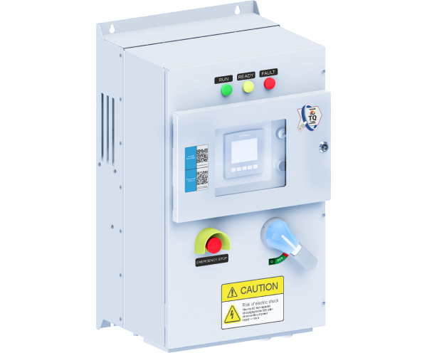
TRIOL AT24 line SR
Place an order
Distinctive benefits
-40 ºC…+50 ºC
Operating temperature
IP55 (NEMA3R) / NEMA4/IP65
Enclosure
removable graphic terminal
Induction supply or SRP controller
Built-in
Input circuit breaker
Remote control terminal
Transient graphs
About product
Specially designed high-tech solution
Variable Frequency Drive Triol AT24 line SR is specially designed for high technological tasks of controlling sucker rod pumps (SRP) with induction motors. Implementing Triol AT24 VFD line SR there is no need to use a rod load sensor, thanks to Triol special algorithms, which allow getting dynamograms with a measurement error of less than 2%.
Automatic flow rate optimization
There is no need to use braking resistors due to drive automatic adaptation to the rod pumping speed. Rocking mill balancing control system and rocking mill mechanical part diagnostic system allows monitoring system status and perform maintenance in time. Automatic flow rate optimization makes it easy to maintain the rate at the optimal level by controlling the well dynamics. It is possible to optimize the process due to archives of dynamograms. The archived data is accessible over the years, whenever you need it.
Remote monitoring and control
Safe operation of Triol AT24 VFD line SR is ensured by blocking from unauthorized pump start and change of system key settings, as well as light and sound alerts for personnel before operation start. Remote monitoring and control via GSM-modem compatible with any application make it easy and convenient for maintenance personnel. It is possible to control the drive via satellite communication as well.
Specifications
| Input | |
|---|---|
| Input voltage, V | 3х380 / 3х480/ 3×690 (-15 % …+10 %) |
| Input frequency, Hz | 50 / 60 (-5 %…+5 %) |
|
Output |
|
| Output current, A | 8.8 … 150 |
| Output frequency, Hz | 0.5…400 |
| Frequency resolution, Hz | 0.1 |
| Acceleration / deceleration time, s | 1 …4000 |
| Overcurrent characteristics | 150 % of rated value for 60 sec |
| Efficiency, % | >97 |
|
Motor control |
|
| Control methods | V/f (volts-per-hertz) (5 reference point) sensorless vector control (open-loop) sensor vector control (close-loop) |
| PWM frequency, kHz | 2…10 |
| Speed range | 1:100 in open-loop system 1:1000 in closed-loop system |
| Speed accuracy (static) | ±10% of motor nominal slip in open-loop system ±0.1 % of rated speed in close-loop system |
| Torque accuracy | ±10% in open-loop system ± 5 % in close-loop system |
| Braking | By frequency
Coasting Dynamic |
| Acceleration / deceleration types | S-curve, linear (3 reference points) |
|
Interface |
|
| Terminal | Options:
Removable graphic terminal with induction power / SRP controller with 3.5″ or 7″ touchscreen |
| Light alarm | “Ready”; “Run”;” Fault”, “Control channel” |
| Push buttons | “Start”; “Stop”; “Program”, navigation keys |
|
Control signals |
|
| Customer supply | 10 V DC, up to 30 mA 24 V DC, up to 150 mA |
| Number of discrete inputs | 8 |
| Discrete inputs | programmable |
| Discrete inputs type | 24 V |
| Number of relay outputs | 4 |
| Relay outputs type | 250 V, 1 A |
| Number of analog inputs | 2, open collector |
| Analog inputs | Programmable 0…10 V / 0…5 mA / 4…20 mA |
| Number of analog outputs | 1 |
| Analog outputs | Programmable 0…10 V / 0…5 mA / 4…20 mA |
|
Communication |
|
| Physical Interface | 2 wire RS-485 for Modbus |
| Communication protocols | Modbus RTU |
| Frame transmission | 115200 bps by default 1200 -250000 bps |
| Data format | 8 bits, 1 stop bit, no parity |
| Number of addresses | 1…255 for Modbus |
| Access | Slave |
|
Protection |
|
| Supply protections | Phase loss, phase sequence fault |
| Motor protections | Overcurrent
Overload Underload Phase loss Current unbalance Encoder open circuit Brake resistor open circuit |
| VFD protections | Overload, Overheating, DC-link undervoltage, DC-link overvoltage, Power switch failure |
| Protections provided SRP controller | Gearbox torque limit
Limiting the effects of gas Limiting the minimum load on the bar Limit the maximum load on the bar Restriction of the minimum and maximum filling of the pump |
| Insulation | Galvanic isolation between power and user circuits |
| Insulation resistance | >1 MQ |
|
Configuration |
|
| Circuit breaker | Built-in |
| DC-link | Up to 11 kW: option, built-in From 15 kW: built-in |
| Braking IGBT- chopper | Up to 11 kW: built-in From 15 kW: option, built-in |
| Input EMC filter (C2) | Option, built-in |
| GSM / GPRS wireless router | Option, built-in |
|
Optional equipment |
|
| Input passive harmonic filter | Option, outdoor |
| Braking resistors | Option, outdoor |
| Output sine filter | Option, outdoor |
|
Construction |
|
| Enclosure | IP55 |
| Cabinet material | Steel |
| Cooling | Forced air |
| Noise level, @ 1 m, dB(A) | <75 |
| Installation | Floor mounting |
| Maintenance | One-side |
| Cable entry | Bottom |
|
Operating conditions |
|
| Operating conditions | Outdoor |
| Operating temperature | -40…+50 °C (-40…+122 F) |
| Storage temperature | -50…+60 °C (-50…+140 F) |
| Relative humidity, % | from 5 to 90 non condensing |
| Altitude, m | up to 1000 m – rated power above 1000 m – with reduced power |


 Google
